ENTITY-RELATIONSHIP DIAGRAMS#
ATTENTION:
- The ERDs in the Knowledge Base are updated as of the 5.04 Release. They will not be updated to reflect any changes done in the 5.05 Release
ERDs or Entity-Relationship Diagrams are a pictorial display of the tables (entities) within the data base structure.
The modules in the application are comprised of many different tables, such as ‘Identity’ or ‘Assignment’. The tables within the system interact with one another and share information. Through these associations, ‘relationships’ form and tables can become dependent on others. The Entity Relationship Diagrams (ERDs) in this manual will explain the interaction that tables in the application have with one another.
Table of Contents
Tables#
Within an ERD, a table is represented as a box containing information about the table.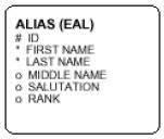 |
Most boxes found in the ERD’s however, provide the user with detailed information about the table.
 |
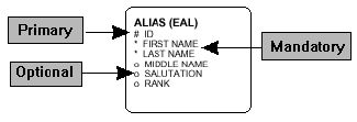
Fields#
- Primary key identified with the # symbol
- Mandatory item identified with the * symbol
- Optional item identified with the O symbol
 |
Shaded Tables#
Sometimes in an ERD, a table will appear with a shaded background. The shaded background indicates that the table is date sensitive. These tables will always have Effective (date) and Expiry (date) columns, although not shown on the ERD. |
The shading will appear gray on a black and white printout; however, it may appear yellow if the ERD is brought up on a computer.
Bold Box#
A table may also appear on an ERD with a bold border. This border indicates that the information in this table is provided as part of the seed data. |
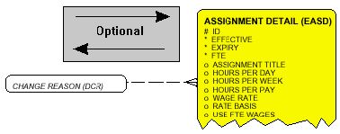
Dotted Line Within a Box#
Occasionally, an ERD will display a box that will hold minimal information and contain a dotted line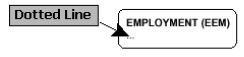 |
This line indicates that the table is explained in detail in another ERD within the same module.
Italicized Text Within a Box#
The ERD’s also display boxes that hold only the table name and alias in italicized text. This indicates that the table is explained in detail in a different module's ERD. |
Lines #
Solid Line Vs. Broken Line#
The connecting lines between tables will be either dotted or a combination of solid and dotted lines. When reading a connecting line, you will notice many instances where a portion of the line is solid and a portion is dotted.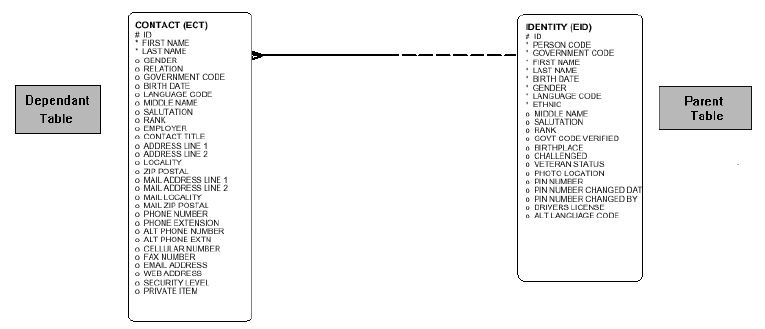 |
The solid line indicates that the Parent table (EID) is MANDATORY for the Dependent table (ECT). This means that the Parent table must be filled BEFORE the Dependent table can be completed. A broken line indicates that the Dependent table (ECT) is OPTIONAL for the Parent table (EID). This means that the Parent table can be completed WITHOUT the Dependent table having been filled.
 |
If the connecting line between the tables is entirely dotted, the tables are optional for each other. This means that either table may be filled before the other.
 |
Written Description#
In addition to the connecting lines, there are also written descriptions of the relationships between the tables. These descriptions will provide a more in-depth explanation of the relationship. |
- The wording running along the TOP part of the line describes the relationship of the left hand table to the right hand table. (e.g. ‘Identity is known by the Alias’)
- The wording running along the BOTTOM part of the line describes the relationship of the right hand table to the left hand table. (e.g. ‘Alias is another name for the Identity’)
The individual defined in EID is ‘KNOWN BY’ the alias in EAL. The alias defined in EAL is ‘ANOTHER NAME FOR’ the individual in EID.
Parent / Dependent Relationship#
Another feature of the connecting lines is the end connections, circled in the diagram below. |
Reading from left to right, we can see that the connection is a ‘One to Many’ relationship.
In this instance, the line starts as a single line at the Entity table and ends in many lines at the Unit table. This means that the entity may have many units associated with it, however, the unit cannot belong to more than one entity. Another way this can be expressed is that the Entity table is the PARENT of the Unit table and the Unit table is the DEPENDENT of the Entity table.
There can be a situation where two tables are parents to each other, which will be explained further on.
Foreign Keys#
Dependent tables will always have a Foreign Key that identifies its parent table.The presence of the "many" branch (also known as crow's feet) indicates this foreign key.
For instance, within the Alias table, there will be a foreign key column (EID_ID) for the parent table, Identity. Parent tables do not keep foreign keys and therefore their dependent tables can only be traced within the Oracle Data dictionary as referential constraints
Two Lines#
Occasionally the tables will have two lines between them. There are two different scenarios for this type of relationshipsParent/Dependent Relationship In the first scenario, one table is the parent with two lines moving towards a dependent table.
 |
In this particular case, the Contact table holds keys to identify the contact’s physical address and mailing address. The two lines originating from the State/Province table indicate that the Contact table will need to use the state/province information on two separate occasions (location and mailing addresses) even though the State/Province information is only given once for each occasion.
The ‘One to Many’ nature of the lines originating from the State/Province table indicates that it is the PARENT to the Contact table. This means that while the state/province information can be applied to many contacts, each contact record, however, can use this data only twice, once for location and once for the mailing address.
Parent/Parent Relationship The second scenario for a two-line relationship between tables is when tables are parents to each other.
 |
The example above shows that the two lines between the tables express that the User table is the parent of the Identity table AND that the Identity table is the parent of the User table; the tables are parents to each other. This simply means that the user identity may have many employee identities attached to it and that the user identity may have may employee identities attached to it. In this case, both tables will have foreign keys for the other table.
Bold Line#
A bold line between two tables indicates that if you delete the record in the parent table, the associated record in the dependent table will be deleted. This is know as a Cascade Delete.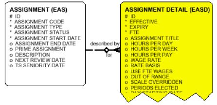 |
In this example, if the assignment record were deleted, the associated assignment detail record would also be deleted automatically.
Curved Line#
A final line format is the curved line that originates and ends at the same table. This represents a self-referencing foreign key.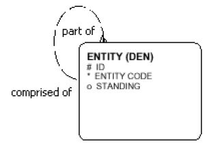 |
In the example above, we can see that the Entity table has a key (DEN_ID) that refers back to itself.
Suppose that your entity has sub-entities:
| Parent Company | = ABC Inc. |
| Subsidiaries | = D Corp. |
| = E Corp. | |
| = F Corp. |
| ID | Entity | Foreign Key DEN_ID | |
|---|---|---|---|
| Parent | 1 | ABC Inc. | Null |
| Dependent | 10 | D Corp | 1 |
| 13 | E Corp | 1 | |
| 27 | F Corp | 1 |
Exclusive Join#
In the diagram below, the Contact table is connected to both the User and Identity tables. Highlighted in the diagram below are two circular symbols joined by a line. This indicates that there is an Exclusive Join with the Contact table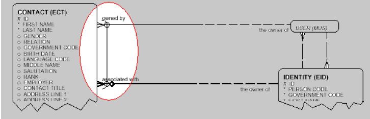 |
This exclusive join means that the contact table may be tied to either the User table or the Identity table, but not both. These tables cannot have the same contact.
Occasionally you will see an exclusive join that isn’t connected to multiple tables. This simply means that for brevity sake, not all dependent tables are displayed on the chart
 |
For example, Distribution can be joined to multiple tables, including the Assignment Detail, Position or Job tables. (Note however, that only the EASD tables is displayed here.)
Diamond Symbol#
On many lines there will be a diamond symbol. This diamond means the parent table cannot be changed on the dependent record. This indicates a non-transferable constraint.In the example above, the Alias record cannot be altered to point to a different Identity.
